Wind tunnel
What it is
A small wind tunnel, about 1 m long, that I am designing and building as my graduation project. Its main job is flow visualization: smoke streaks running past an airfoil in the test section, watched through an acrylic window, together with a basic pressure measurement from a sensor.
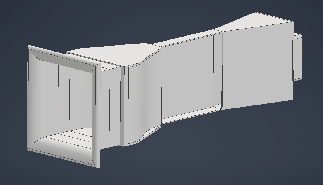
The tunnel is flat on purpose. Its height stays at 200 mm along the whole channel and only the depth changes, down to 30 mm in the test section. The smoke streaks therefore run in a single plane and stay sharp through the window. The airfoil spans the test section from wall to wall, so there are no wingtips and the flow around it is close to two-dimensional — the same case XFOIL simulates, the tool I used for the RC plane and to check Airfoil AI.
How it works
The channel. It is an open-circuit suction tunnel: the fan sits at the far end and pulls room air through the whole channel, so the swirl it creates leaves the tunnel instead of passing through the test section. A rounded inlet leads into the settling chamber, where a honeycomb of drinking straws straightens the flow and fine screens break up the eddies. The smoke rake goes behind the last screen — in front of it, the screens would break the smoke streaks up. The contraction then speeds the air up and evens it out, and the diffuser slows it down again in front of the fan.
Design rules. I chose the test section — 200 × 30 × 230 mm, for an airfoil with a 50 mm chord — and the rest of the tunnel is sized from it using design rules for small low-speed wind tunnels from the literature. The most complex part is the contraction. Its walls follow a fifth-order polynomial, the shape that came out best in a NASA report on contraction design. It has zero slope and zero curvature at both ends, so the wall blends into the settling chamber and the test section without a kink where the flow could separate.
Electronics. An ESP32 reads a potentiometer and sets the speed of a 120 mm Delta AFB1212SHE fan through its PWM input, with a 330 Ω resistor on the signal line — a cheap precaution in front of an expensive fan. A single 12 V, 3 A supply powers the fan directly and the ESP32 through a 5 V step-down converter, with a common ground for both.
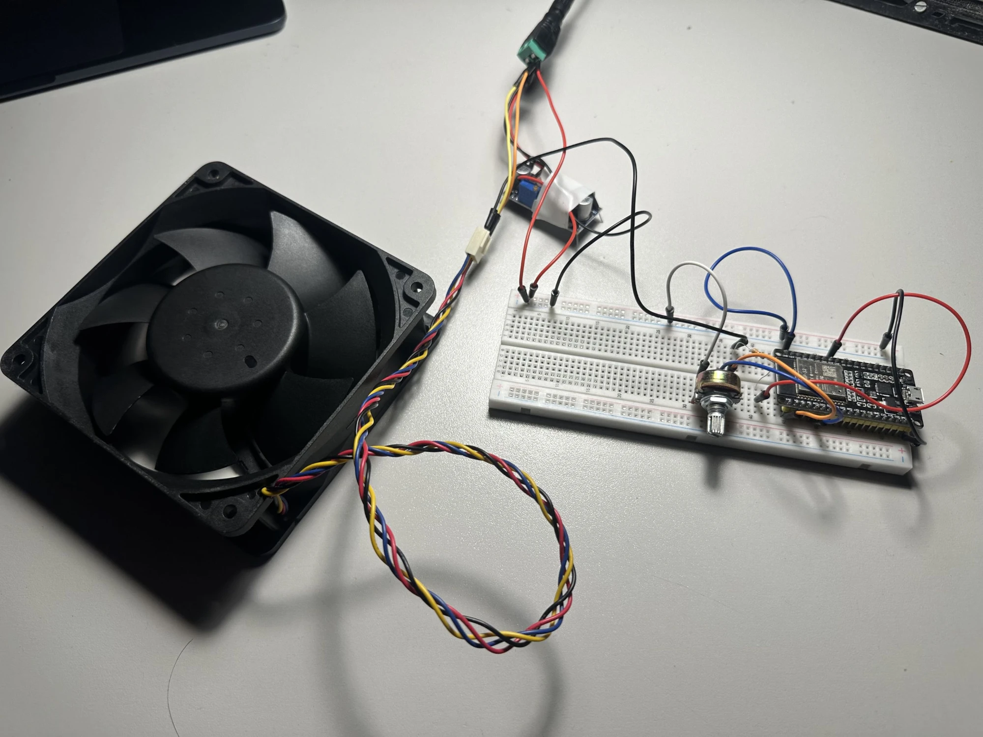
One finding from testing the prototype: 0 % on the potentiometer does not mean stopped. The fan keeps turning slowly even with the PWM duty cycle at zero — a property of the fan, not a bug in the code — so the tunnel gets a main power switch.
Status — November 2026
The CAD model and the fan control prototype are done, and building the tunnel is the current step. The plan from here:
- Building the tunnel — November 2026
- Finishing the electronics, including the pressure sensor — December 2026
- Final assembly and testing — January 2027
- Technical documentation — February 2027
- Submission — April 2027
Links
- Mehta & Bradshaw (1979) — design rules for small low-speed wind tunnels, the basis for sizing the tunnel.
- Bell & Mehta (1988) — the NASA report on contraction design that the contraction shape comes from.