RC Plane
What it is
A fixed-wing RC aircraft built from scratch as my school-year project — no kit, no commercial flight controller. The project covers the whole development cycle: aerodynamic analysis in XFOIL and XFLR5, geometric design of the wing and tail, 3D-printed construction, onboard electronics, and a custom radio link with firmware for both the plane and the controller.
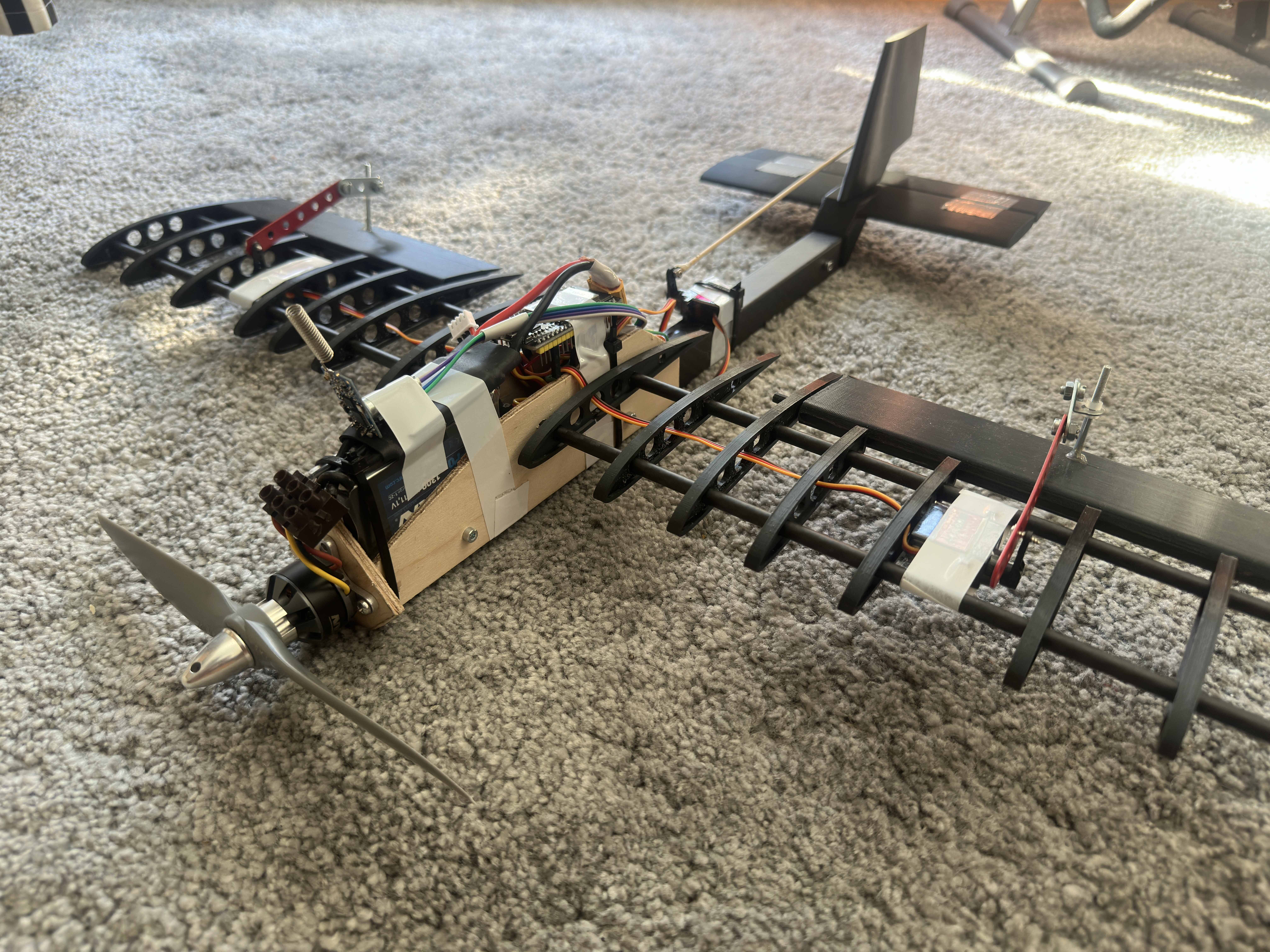
The aircraft has a 600 mm wingspan, weighs 632 g, and uses a NACA 4412 main wing, a carbon-fiber spine and spars, and 3D-printed ribs and tail surfaces. The hand-built controller communicates with the plane over a 433 MHz link. All design decisions are documented in the technical report linked below.
How it works
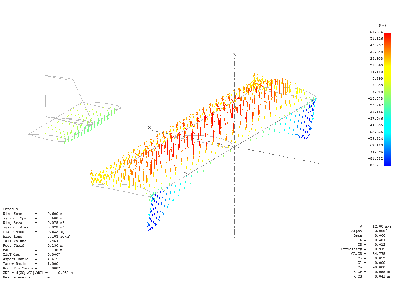
Aerodynamics. The main wing uses a cambered NACA 4412 airfoil and the tail a symmetric NACA 0012, analysed at the low Reynolds numbers (80,000–110,000) where RC models actually fly. I verified the whole configuration with a VLM1 simulation in XFLR5. The neutral point came out at 51 mm, the CG is placed at 41 mm, giving a static margin of 7.7 % which is right inside the recommended 5–15 % stability window. Stall speed calculated from the measured mass is 11.1 m/s, with a 12 m/s cruise speed on top of it.
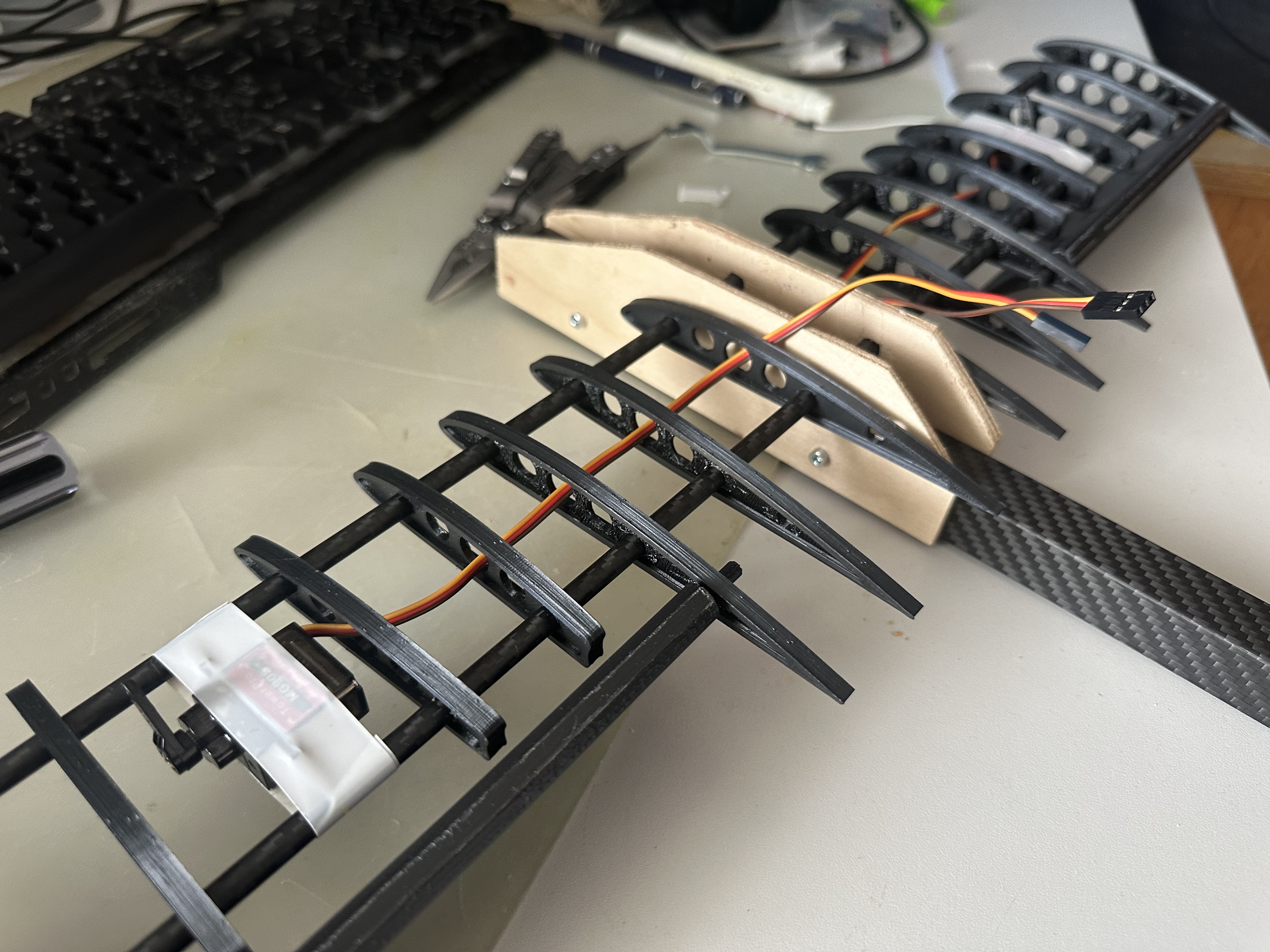
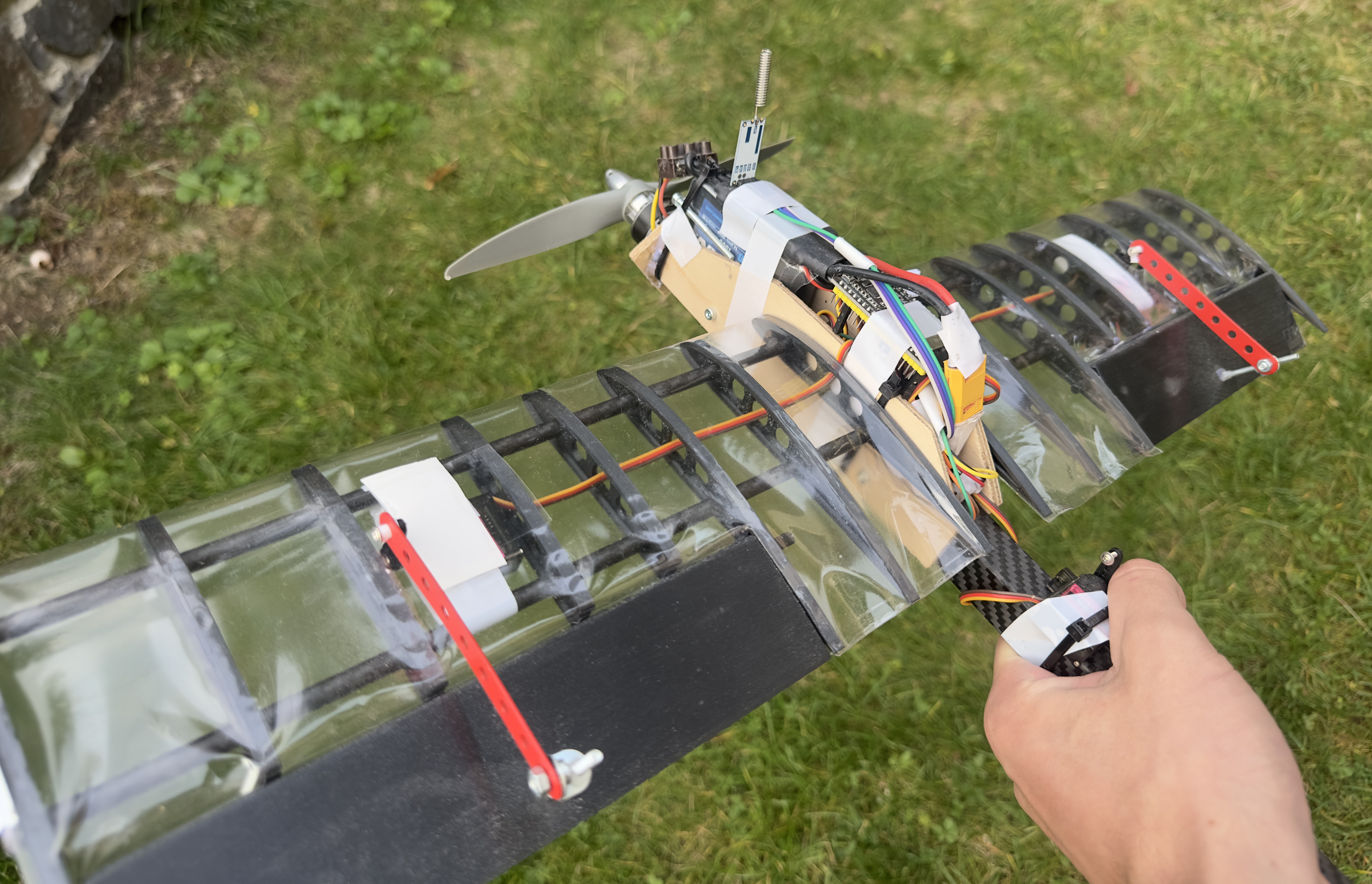
Structure. The fuselage is a square carbon composite tube; the wing is a rib-and-spar sandwich with sixteen 3D-printed NACA 4412 ribs threaded onto two 6 mm carbon rods, covered with heat-shrink film. Ailerons and elevator are driven by three MG90S metal-gear servos through mechanical pushrods.
Electronics and radio. Both the plane and the controller run on an ESP32. The controller reads two joysticks through the 12-bit ADC, packs the values into a 6-byte binary struct, and transmits them over an HC-12 module at 433 MHz, 20 times per second. The receiver decodes the packet and maps it to PWM signals for the servos and the 40 A ESC driving the brushless motor. A fail-safe cuts the throttle and centers all control surfaces if the link drops for more than a second. The controller itself is a gutted old drone transmitter that I rebuilt around the ESP32.
Key numbers
- Wingspan 600 mm, wing area 0.078 m², mass 632 g
- Static margin 7.7 %
- Stall speed 11.1 m/s, thrust-to-weight 0.78
- Radio link: 433 MHz, 20 Hz update rate, fail-safe on link loss
- ~10 min estimated flight time on a 3S 1300 mAh LiPo
What I learned
The biggest lesson came from a mistake. After assembly, the first version of the 3D-printed tail weighed 88 g and shifted the center of gravity 35 mm behind the neutral point — the plane was statically unstable and would have been unflyable. Diagnosing that meant actually understanding the difference between the neutral point (pure geometry) and the CG (mass distribution), rather than just plugging numbers into formulas. The fix was reprinting the tail at minimal infill and adding a small nose ballast, bringing the static margin back into the safe range. Mass budgeting is now the first thing I would do in any future design, not the last.
Beyond that, I learned how to run and interpret low-Reynolds simulations and know their limits (why I used an inviscid method for the 3D analysis), how to design a binary radio protocol and why a fail-safe is non-negotiable in anything that flies, and how to take a project through a full engineering cycle — requirements, analysis, design, manufacturing, debugging, and documentation — as one person.
Update — October 2026
Since the initial build, the plane has finally flown. I don't have footage of the flight, because it was meant as a quick test to check that everything worked before recording. The plane flew well and was stable, but after a rough landing a control linkage broke and the plane was damaged. I will repair it and record a proper flight video when I have time.
Links & downloads
- Source code on GitHub — firmware for both the transmitter and the receiver, STL models and wiring diagrams.
- Technical documentation ENG (PDF) — full calculations, model design, choice of materials, electrical schemes and software.
- Technical documentation CZE (PDF) — original Czech version.